86-0574-62162348
Categories
- Power Cord
- America Power Cords
- Europe Power Cords
- Australia Power Cords
- UK Power Cords
- Korean Power Cords
- Japan Power Cords
- Italy Power Cords
- South Africa Power Cords
- Swiss Power Cords
- Argentina Power Cords
- Brazil Power Cords
- Israel Power Cords
- Denmark Power Cords
- China Power Cords
- Russia Power Cords
- Singapore Power Cords
- Saudi Power Cords
- Indonesia Power Cords
- Thailand Power Cords
- IEC 60320 Power Cords
- Locking Power Cord
- Dryer Power Pord
- Industry Plug
- Extension Cord
- Rubber Insulated Sheathed Flexible Cord
- PVC Flexible Power Cable
- Power Strip
pleated filter cartridge factory
high flow filter cartridge
large flow filter cartridge
membrane pleated filter cartridge
capsule filter suppliers
capsule filter 0.2 micron
capsule filter price
pvc dildo
fat pocket pussy
lamb skin dildo
mushroom head dildo
huge dildo
water filter cartridge
- Power Cord
- America Power Cords
- Europe Power Cords
- Australia Power Cords
- UK Power Cords
- Korean Power Cords
- Japan Power Cords
- Italy Power Cords
- South Africa Power Cords
- Swiss Power Cords
- Argentina Power Cords
- Brazil Power Cords
- Israel Power Cords
- Denmark Power Cords
- China Power Cords
- Russia Power Cords
- Singapore Power Cords
- Saudi Power Cords
- Indonesia Power Cords
- Thailand Power Cords
- IEC 60320 Power Cords
- Locking Power Cord
- Dryer Power Pord
- Industry Plug
- Extension Cord
- Rubber Insulated Sheathed Flexible Cord
- PVC Flexible Power Cable
- Power Strip
Future Products
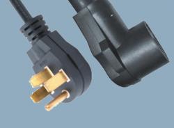
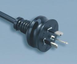
power cord having an insertion plug
In a conventional power cord, for example, blades are connected to a plurality of conductors projected (exposed) from the leading end of cord, and the base side of blades and leading end side of cord are covered with vinyl chloride, and a plug isformed.
It is excellent in forming performance and is inexpensive, but when the plug of vinyl chloride is inserted in the socket and left over for a long period, dust or moisture sticks to blades, andweak current begins to flow, and the resin texture is broken and a carbide conductive path may be formed to short-circuit blades, finally leading to outbreak of fire, and hence it had a problem of low reliability in tracking resistance.
As a result, the hard resin for composing the core is excellent in heat resistance, internal deterioration by heat is slight, and tracking fire can be prevented, thereby presenting a power cord freefrom deviation of blade interval, and capable of preventing deformation or deviation during plugging and unplugging operation.
It is a different object of the invention to present a power cord having a locking structure of preventing separation of the two by integral forming (integration) of plug between the core and plug, in which the locking structure prevents gapforming or separation between the core and plug if the plug is handled roughly on the socket.
As a result, since the resin for forming the core is hard, it is easyto hold the core, and it is possible to form without deviating the blade configuration. Since the core is covered with outer skin of plug, the plug is formed at least in two steps, and partial thickening is avoided, and it prevents inconvenience ofdeviation of blade interval due to shrinkage after forming. Further, since the wall thickness of the plug is thin, cooling time in the molding die in each forming process can be shortened, and the forming cycle time is shorter, and an economicalmanufacturing method of power cord is presented.
It is a different object of the invention to present a manufacturing method of power cord capable of bonding the both securely and firmly by forming a locking structure for preventing separation of the two by integrally forming the plug, betweenthe core and plug, in the plug forming process.
By positioning the core 15 at the front side of the plug 14, and forming the front part 15a of the core 15 so as to be exposed on the front side of the plug 14 (in this case, the front part 15a to be flush with the front side of the plug 14), theplug front part is formed of a resin strong in tracking resistance such as polyamide, polybutadiene, or polypropylene, and if dust or moisture sticks to blades 13, 13 at the front side of the plug 14, and weak current begins to flow, it is effective toprevent breakage of resin texture by weak current or formation of carbide conductive path, and tracking fire is not caused by these reasons, so that a high reliability in tracking resistance is assured.
On the other hand, according to the manufacturing method of the power cord 11 of the embodiment, the power cord 11 is manufactured in plural steps including a core forming process (see FIG. 6) of ejecting and forming a core 15 by hardthermoplastic resin such as polyamide, polybutadiene, or polypropylene, by inserting the base 13a of blade 13, or from the base 13a to the leading end of cord 12 (leading end of insulator 12), in a state being spaced by a specified distance, and a plugforming process (see FIG. 8) of ejecting and forming a plug 14 by soft thermoplastic resin by inserting the core 15 (specifically pre-formed piece 20 shown in FIG. 20).
Further, the die (upper pattern 17, 21, lower pattern 18, 22) used in ejecting and forming process divides the plug 14 into two halves, and parting lines PL1, PL2 are formed at positions not dividing the blades 13, and thereby positioning ofblades 13 is excellent, and processing and positioning of upper and lower die patterns are also easy.
- Contact Us
- Simen Twon,Yuyao City,Zhejiang,China,315472
- 86-0574-62162348
- 86-0574-62160100
- [email protected]
- hoobo.show1
- Terms and Conditions
- Privacy Statement
- Need help
- Home
- About us
- Products
- Download
- News
- Equipments
- Tech-Documnets
- Contact
- Products
- Power Cord
- IEC 60320 Power Cords
- Locking Power Cord
- Dryer Power Pord
- Industry Plug
- Extension Cord
- Rubber Insulated Sheathed Flexible Cord
- PVC Flexible Power Cable
- SUBSCRIBE
- Join us and get detail information,technical parameter and new products etc.
- [email protected]
- hoobo.show1
- 86-0574-62162348
- 86-0574-62162348


