86-0574-62162348
Categories
- Power Cord
- America Power Cords
- Europe Power Cords
- Australia Power Cords
- UK Power Cords
- Korean Power Cords
- Japan Power Cords
- Italy Power Cords
- South Africa Power Cords
- Swiss Power Cords
- Argentina Power Cords
- Brazil Power Cords
- Israel Power Cords
- Denmark Power Cords
- China Power Cords
- Russia Power Cords
- Singapore Power Cords
- Saudi Power Cords
- Indonesia Power Cords
- Thailand Power Cords
- IEC 60320 Power Cords
- Locking Power Cord
- Dryer Power Pord
- Industry Plug
- Extension Cord
- Rubber Insulated Sheathed Flexible Cord
- PVC Flexible Power Cable
- Power Strip
pleated filter cartridge factory
high flow filter cartridge
large flow filter cartridge
membrane pleated filter cartridge
capsule filter suppliers
capsule filter 0.2 micron
capsule filter price
pvc dildo
fat pocket pussy
lamb skin dildo
mushroom head dildo
huge dildo
water filter cartridge
- Power Cord
- America Power Cords
- Europe Power Cords
- Australia Power Cords
- UK Power Cords
- Korean Power Cords
- Japan Power Cords
- Italy Power Cords
- South Africa Power Cords
- Swiss Power Cords
- Argentina Power Cords
- Brazil Power Cords
- Israel Power Cords
- Denmark Power Cords
- China Power Cords
- Russia Power Cords
- Singapore Power Cords
- Saudi Power Cords
- Indonesia Power Cords
- Thailand Power Cords
- IEC 60320 Power Cords
- Locking Power Cord
- Dryer Power Pord
- Industry Plug
- Extension Cord
- Rubber Insulated Sheathed Flexible Cord
- PVC Flexible Power Cable
- Power Strip
Future Products
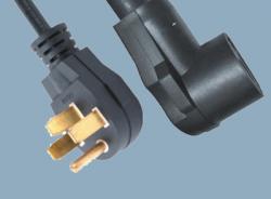
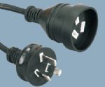
An extension power cord comprising
The use of electrical connecting devices is known in the prior art. More specifically, electrical connecting devices heretofore devised and utilized for the purpose of interconnecting temporary extension power cords are known to consist basically of familiar, expected and obvious structural configurations, notwithstanding the myriad of designs encompassed by the crowded prior art which have been developed for the fulfillment of countless objectives and requirements.
The locking connector for an extension power cord according to the present invention substantially departs from the conventional concepts and designs of the prior art, and in so doing provides an apparatus primarily developed for the purpose of providing a liquid resistant positive locking plug and receptacle combination whereby preventing unwanted separation of a plurality of connected together extension power cords, the locking connector being suitable for home and commercial use indoors and outdoors.
As illustrated by the background art, efforts are continuously being made in an attempt to develop devices for interconnecting temporary extension power cords. No prior effort, however, provides the benefits attendant with the present invention.
As such, the general purpose of the present invention, which will be described subsequently in greater detail, is to provide a new locking connector for an extension power cord apparatus and method which has all the advantages of the prior art electrical connecting devices and none of the disadvantages.
For the purpose of summarizing the invention, the invention may be incorporated into a locking connector for an extension power cord for providing a liquid resistant positive locking plug and receptacle combination whereby preventing unwanted separation of a plurality of connected together extension power cords. The locking connector is suitable for home and commercial use, indoors and outdoors.
The plug body has a planar front face with an o-ring sealing surface formed thereon. A plurality of external threads formed on the sidewall of the plug body adjacent the front face. An electrical cord entry aperture is formed in a rear end of the plug body. A plurality of male electrical connector prongs projects from the front face of the plug body.
There are, of course, additional features of the invention that will be described hereinafter and which will form the subject matter of the claims appended hereto. In as much as the foregoing has outlined rather broadly the more pertinent and important features of the present invention in order that the detailed description of the invention that follows may be better understood so that the present contribution to the art can be more fully appreciated.` It should be appreciated by those skilled in the art that the conception and the disclosed specific methods and structures may be readily utilized as a basis for modifying or designing other structures for carrying out the same purposes of the present invention.
An even further object of the present invention is to provide a new locking connector for an extension power cord which is susceptible of a low cost of manufacture with regard to both materials and labor, and which accordingly is then susceptible of low prices of sale to the consuming public, thereby making such locking connectors for an extension power cord economically available to the buying public.
Many other beneficial results can be attained by applying the disclosed invention in a different manner or by modifying the invention within the scope of the disclosure. Accordingly, other objects and a fuller understanding of the invention may be had by referring to the summary of the invention and the detailed description of the preferred embodiment in addition to the scope of the invention defined by the claims taken in conjunction with the accompanying drawings.
- Contact Us
- Simen Twon,Yuyao City,Zhejiang,China,315472
- 86-0574-62162348
- 86-0574-62160100
- [email protected]
- hoobo.show1
- Terms and Conditions
- Privacy Statement
- Need help
- Home
- About us
- Products
- Download
- News
- Equipments
- Tech-Documnets
- Contact
- Products
- Power Cord
- IEC 60320 Power Cords
- Locking Power Cord
- Dryer Power Pord
- Industry Plug
- Extension Cord
- Rubber Insulated Sheathed Flexible Cord
- PVC Flexible Power Cable
- SUBSCRIBE
- Join us and get detail information,technical parameter and new products etc.
- [email protected]
- hoobo.show1
- 86-0574-62162348
- 86-0574-62162348


